Sunday, October 27, 2013

Surgical Screw Failure Analysis, Metal Fatigue


 Read Consulting performed a metal failure analysis on two surgical screws that were used to hold wire for a surgical implanted back support system. These titanium screws failed after less than one year after the surgical implant.The failure analysis determined that both screws failed at the minor diameter due to  metal fatigue in bending. In one case there was a machining mark that was associated with the initiation of the fatigue failure. This machining mark acted as a stress riser that magnified the applied stress. In addition, the bending stresses were higher on both screws because these titanium screws were not  inserted completely.

Labels: , , , , ,

Thursday, October 27, 2011

Northern California Failure Expert Witness Describes Tubing Failure


An interesting failure of steel tubing was observed when 1 3/4" diameter A513 Type 5 steel tubing was being bent in a tubing bender. In this case the tube was clamped into the bender in the wrong location. At this time the clamp bolt had made an indentation (nick) in the pipe surface. The pipe was released and moved. The "nick" ended up on the tensile surface (i.e. convex side of the bend) during bending. As the tubing was being formed it broke in a ductile manner. A513 Type 5 steel is work hardened and therefore has little ductility, and it cannot survive bending if the surface has been damaged. The appropriate tubing should have been made of C 1020 mild steel. Upper left is a photograph of the nick on the convex side of the bend. The failure is interesting because it is a progressive failure that was caused by non-cyclic stresses (i.e. it is not metal fatigue). In addition, there are faint crack arrest lines that show the progression of the ductile failure. The failure surface almost looks like metal fatigue. This fsailure did not occur when C 1020 tubing was treated in the same manner. This failure was the result of improper material selection. It is not the result of a manufacturing defect.

Labels: , , ,

Friday, January 01, 2010

Failure Analysis Expert Witness Analyzes a Pipe Fatigue Failure


Failure analysis expert analyzes a pipe failure. In this case the failed brass pipe supported a gauge. The gauge was cantilevered on the 6" long pipe and valve assembly. This assembly was attached to a pump, and the pump vibrations acted on the assembly and caused a metal fatigue failure to initiate ar the root of the male pipe thread where the thread exited the 'T' fitting. This is the most vulnerable point. The moment is maximum at this point and the root of the thread was a stress concentrator that magnified the stresses caused by the vibrations. The photographs above summarize the failure. Upper left shows an overview of the failure. The pipe failure occured where the pipe entered into the 'T' fitting. Upper right is an 8X photomicrograph ofthe fracture surface. The fatigue failure initiated at the root of the pipe thread. It then proceeded to the left as shown by the arrows. Fundimentally, the vibrating weight of the cantilevered, unsupported gauge caused the failure.

Labels: , , , ,

Tuesday, March 31, 2009

Failure Analysis Expert Discusses Metal Fatigue


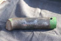
Failure analysis was performed on a failed pin from a large tractor. The upper right gives an overview of the pin. Upper left is a close up of the fracture surface. The fatigue crack originated at the top of the photo and progressed downward until the final overload failure.


Labels: , , ,